Efficiency Of Cuk Converter Equations And Expressions
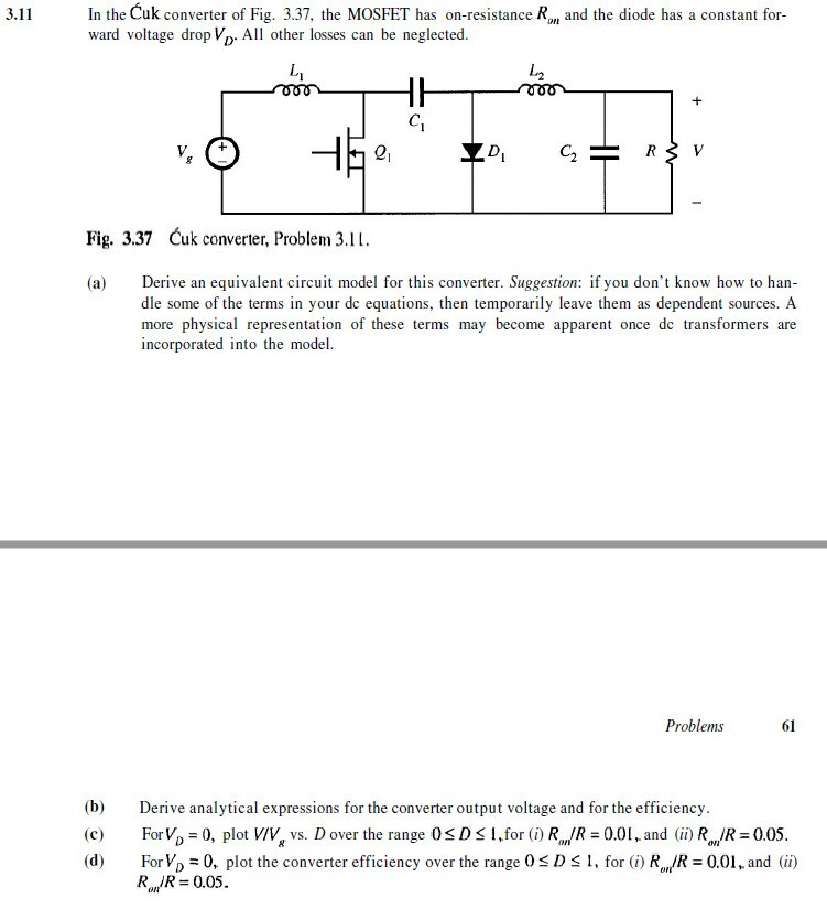
The converter conversion efficiency of the Cuk converter is 86.26%. PV module is modeled based on the electrical Equations (2.1) and (2.2) to provide voltage and current to the Cuk converter and the micro-controller simultaneously. Answer to In the Cuk converter of Fig. The MOSFET has on. Terms in your dc equations. 0, plot the converter efficiency over the range 0.
Download Jeta Logo Designer 1.0A [Full] Crack. Operating System: Windows XP,Vista,7,8,8.1,10 File Size: 2.27MB System Requirements: Intel Pentium 4 or higher. Atleast 512MB RAM Number of Downloads: 78. Jeta logo designer torrent.
Abstract The principal objective of this work on modeling and analysis of switching dc-to-dc converters and regulators is to obtain a linear model (either through state-space or linear circuit description), subject to appropriate restrictions, for the inherently nonlinear power state in which the dc conversion is accomplished. A general unified approach to modeling and analysis of switching dc-to-dc converters is developed which is directly applicable to any dc-to-dc operating in either of two conduction modes (continuous or discontinuous inductor current), and which results in a final dynamic linear model either in terms of state-space equations or in terms of their corresponding linear circuit models. In particular, in Part I this analysis technique, called state-space averaging, is applied to the continuous conduction mode of converter operation, while in Part II appropriate extension of the method to the discontinuous conduction mode is made. In each case, the culmination of modeling and analysis is achieved in the development of canonical circuit models which represent any such converter regardless of its detailed configuration. The insights that emerge from the general state-space modeling approach (Parts I and II) lead in Parts III and IV to the design of new converter topologies through the study of generic properties of the cascade connection of basic buck and boost converters. This study paves the way in Part IV to the discovery of a new switching converter based upon capacitive rather than the usual inductive energy transfer. The new converter is shown to have substantial advantages over the conventional converters in its class in efficiency, performance, and also in size and weight.
Bothe the state-space averaged models and their corresponding circuit realizations provide the circuit designer with a powerful tool for analysis of existing converters as well as for synthesis of new converter topologies.
The basic schematic of an inverting buck–boost converter. The buck–boost converter is a type of that has an output voltage magnitude that is either greater than or less than the input voltage magnitude. It is equivalent to a using a single inductor instead of a transformer.
Two different topologies are called buck–boost converter. Both of them can produce a range of output voltages, ranging from much larger (in absolute magnitude) than the input voltage, down to almost zero. The inverting topology The output voltage is of the opposite than the input.
This is a with a similar circuit topology to the and the. The output voltage is adjustable based on the of the switching transistor. One possible drawback of this converter is that the switch does not have a terminal at ground; this complicates the driving circuitry.
However, this drawback is of no consequence if the power supply is isolated from the load circuit (if, for example, the supply is a battery) because the supply and diode polarity can simply be reversed. When they can be reversed, the switch can be on either the ground side or the supply side. A combined with a The output voltage is typically of the same polarity of the input, and can be lower or higher than the input. Such a non-inverting buck-boost converter may use a single inductor which is used for both the buck inductor mode and the boost inductor mode, using switches instead of diodes. Sometimes called a 'four-switch buck-boost converter', it may use multiple inductors but only a single switch as in the and topologies. The basics of the 4-switch topology The 4-switch converter combines the buck and boost converters.
- вторник 18 декабря
- 58